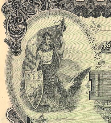
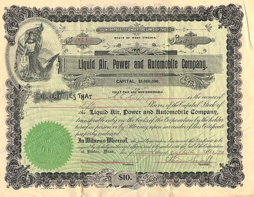
Beautiful certificate from the Liquid Air, Power and Automobile Company issued in 1899. This historic document was printed by Thorp & Martin Banknote Company and has an ornate border around it with a vignette of a allegorical woman. This item has the signatures of the Company's President, Edwin Planta and Treasurer, Thomas Sewall and is over 118 years old. 
Certificate Vignette Liquid Air was the brand name of an unusual automobile produced by a joint American/English concern between 1899 and 1902. The first factory opened in Boston, Massachusetts in 1899, and its owners claimed that they could construct a car that would run a hundred miles on liquid air. By 1901 the company had gone into receivership. In 1902 the product was demonstrated by its designer, Hans Knudsen, at a show in London; apparently the automobile that was shown was a modified Locomobile steamer. Here it was claimed to run 40 miles (64 km) at 12 mph (19 km/h) on 18 US gal (68 L; 15 imp gal) of liquid air, sold at a shilling a gallon.
The following patent was made on behalf of the company: United States Patent Office. THOMAS SEWALL, OF BOSTON, MASSACHUSETTS. INSULATING-RECEPTACLE FOR HOLDING LIQUID AIR. SPECIFICATION forming part of Letters Patent Wo. 665,349, dated January 1, 1901. Application filed June 16,1899, Serial No. 720,744. IMomodelJ To all whom, it may concern: Be it known that I, Thomas Sewall, a citizen of the United States, and a resident of Boston, in the county of Suffolk and State of 5 Massachusetts, have invented certain new and useful Improvements in Insulating Receptacles for Holding Liquid Air, of which the following is a specification. The object of my invention is to produce 10 an insulating vessel or receptacle for containing liquid air and causing the vapor or gas arising from said liquid in the vessel or receptacle to circulate around the outside of said vessel, thus maintaining a low tempera- 15 ture within and around same to reduce the vaporization to a minimum. The invention consists of a vessel or receptacle closed at the bottom and also at the top, except for a small central opening, the out- 20 side of said vessel being formed with ribs or other protuberances, preferably in spiral form, extending from the top to the bottom, so as to cause the vapor or gas escaping from the vessel to circulate around same, said ves- 25 sel "being inclosed within a casing having an. open bottom and a top having a small central opening, said casing being formed on its outer surface with spiral ribs or other protuberances that cause the vapor or gas to as- 30 cend in an upward direction, said casing being inclosed within an outer casing having a solid bottom formed with a number of small knobs or protuberances upon which the bottom of the inner vessel and the inner casing 35 rests, so as to form a passage for the vapor or gas, and a cover for inclosing the upper portion of the apparatus, as hereinafter set forth. Referring to the accompanying drawings, 40 Figure 1 represents a vertical section taken through a liquid-air vessel or receptacle embodying my invention. Fig. 2 is an elevation of the same with the cover in the closed position. Fig. 3 is an elevation of the ves- 45 sel or receptacle for containing the liquid air. Fig. 4 is an elevation of the casing inclosing the liquid-air vessel. Fig. 5 is a plan or top view of same. Fig. 6 is a plan view of the outer casing. 50 A represents the vessel or receptacle in which the liquid air is placed. This vessel has a solid bottom a and at its upper end is contracted to form a neck a', closed at its upper end by a disk a2, in which a small hole a3 is formed. The outer periphery of the 55 vessel is formed with spiral ribs a4, or, if desired, vertical ribs or other protuberances or any other means for forming a passage might be employed in order to allow the vapor escaping from the vessel to circulate around 60 same. B is a casing the internal diameter of which is of a size to admit the vessel or receptacle A, and it is also formed with a neck 6, closed at its upper end by a disk &', the edges of 65 which project beyond the neck 6, so as to form a flange, in which are formed two recesses V, said flanges being beveled on their under side for the purpose hereinafter described. This disk is also formed with a 70 small hole 53, and around the body of this casing are arranged spiral ribs 6* or vertical ribs, or otherprotuberances may be em ployed, if desired. C is an outer casing open at the top and 75 having small knobs or protuberances c on the inside of the bottom, upon which rest the lower ends of the vessel A and casing B. D is a cover of a form to fit over the neck of the casing B and open at its lower end and 80 of a diameter equal to the diameter of the outer casing c. The inner surface of this cover is formed with two projections d of a width to fit into the recesses or spaces ft8, and in the upper portion, above said projections, 85 is arranged a disk, of felt E or other soft material, so that when the cover is placed in position the two projections d pass to the under side of the flanges V, and by giving the cover a slight turn the cover is, by the bevel of the go flanges, drawn down, so that the felt E fits tightly upon the disk 6', thus closing the opening b8, while the bottom of the cover will be held a short distance above the upper edge of the outer casing C, as shown in Fig. 2. 95 When in use, liquid air is placed in the vessel or receptacle A, and as the same vaporizes the vapor passes out of the opening a3 into the space between the outside of the vessel A and the inner side of the casing B and is, by 100 the spiral ribs a4, conducted to the bottom and then passes up the space between the casing B and the outer casing, it ascending in spiral form by means of the ribs &4. No. 665,349. (No Model.) T. SEWALL Patented Jan. I, 1901. INSULATING RECEPTACLE FOR HOLDING LIQUID AIR. (Application filed June 16, 1899.)
History from Wikipedia and OldCompany.com (old stock certificate research service).

Certificate Vignette
The following patent was made on behalf of the company: United States Patent Office. THOMAS SEWALL, OF BOSTON, MASSACHUSETTS. INSULATING-RECEPTACLE FOR HOLDING LIQUID AIR. SPECIFICATION forming part of Letters Patent Wo. 665,349, dated January 1, 1901. Application filed June 16,1899, Serial No. 720,744. IMomodelJ To all whom, it may concern: Be it known that I, Thomas Sewall, a citizen of the United States, and a resident of Boston, in the county of Suffolk and State of 5 Massachusetts, have invented certain new and useful Improvements in Insulating Receptacles for Holding Liquid Air, of which the following is a specification. The object of my invention is to produce 10 an insulating vessel or receptacle for containing liquid air and causing the vapor or gas arising from said liquid in the vessel or receptacle to circulate around the outside of said vessel, thus maintaining a low tempera- 15 ture within and around same to reduce the vaporization to a minimum. The invention consists of a vessel or receptacle closed at the bottom and also at the top, except for a small central opening, the out- 20 side of said vessel being formed with ribs or other protuberances, preferably in spiral form, extending from the top to the bottom, so as to cause the vapor or gas escaping from the vessel to circulate around same, said ves- 25 sel "being inclosed within a casing having an. open bottom and a top having a small central opening, said casing being formed on its outer surface with spiral ribs or other protuberances that cause the vapor or gas to as- 30 cend in an upward direction, said casing being inclosed within an outer casing having a solid bottom formed with a number of small knobs or protuberances upon which the bottom of the inner vessel and the inner casing 35 rests, so as to form a passage for the vapor or gas, and a cover for inclosing the upper portion of the apparatus, as hereinafter set forth. Referring to the accompanying drawings, 40 Figure 1 represents a vertical section taken through a liquid-air vessel or receptacle embodying my invention. Fig. 2 is an elevation of the same with the cover in the closed position. Fig. 3 is an elevation of the ves- 45 sel or receptacle for containing the liquid air. Fig. 4 is an elevation of the casing inclosing the liquid-air vessel. Fig. 5 is a plan or top view of same. Fig. 6 is a plan view of the outer casing. 50 A represents the vessel or receptacle in which the liquid air is placed. This vessel has a solid bottom a and at its upper end is contracted to form a neck a', closed at its upper end by a disk a2, in which a small hole a3 is formed. The outer periphery of the 55 vessel is formed with spiral ribs a4, or, if desired, vertical ribs or other protuberances or any other means for forming a passage might be employed in order to allow the vapor escaping from the vessel to circulate around 60 same. B is a casing the internal diameter of which is of a size to admit the vessel or receptacle A, and it is also formed with a neck 6, closed at its upper end by a disk &', the edges of 65 which project beyond the neck 6, so as to form a flange, in which are formed two recesses V, said flanges being beveled on their under side for the purpose hereinafter described. This disk is also formed with a 70 small hole 53, and around the body of this casing are arranged spiral ribs 6* or vertical ribs, or otherprotuberances may be em ployed, if desired. C is an outer casing open at the top and 75 having small knobs or protuberances c on the inside of the bottom, upon which rest the lower ends of the vessel A and casing B. D is a cover of a form to fit over the neck of the casing B and open at its lower end and 80 of a diameter equal to the diameter of the outer casing c. The inner surface of this cover is formed with two projections d of a width to fit into the recesses or spaces ft8, and in the upper portion, above said projections, 85 is arranged a disk, of felt E or other soft material, so that when the cover is placed in position the two projections d pass to the under side of the flanges V, and by giving the cover a slight turn the cover is, by the bevel of the go flanges, drawn down, so that the felt E fits tightly upon the disk 6', thus closing the opening b8, while the bottom of the cover will be held a short distance above the upper edge of the outer casing C, as shown in Fig. 2. 95 When in use, liquid air is placed in the vessel or receptacle A, and as the same vaporizes the vapor passes out of the opening a3 into the space between the outside of the vessel A and the inner side of the casing B and is, by 100 the spiral ribs a4, conducted to the bottom and then passes up the space between the casing B and the outer casing, it ascending in spiral form by means of the ribs &4. No. 665,349. (No Model.) T. SEWALL Patented Jan. I, 1901. INSULATING RECEPTACLE FOR HOLDING LIQUID AIR. (Application filed June 16, 1899.)
History from Wikipedia and OldCompany.com (old stock certificate research service).


